• Skip to primary navigation
  • Skip to main content
  • Skip to primary sidebar

N4REE - Minimalist Ham

Code rehab forever - Make CW a 2nd language

  • Home
  • About
  • Contact

T41-EP Transceiver

T41-EP SDT “Pop-Pop” (3 of ?)

July 20, 2024 by Bob Easton Leave a Comment

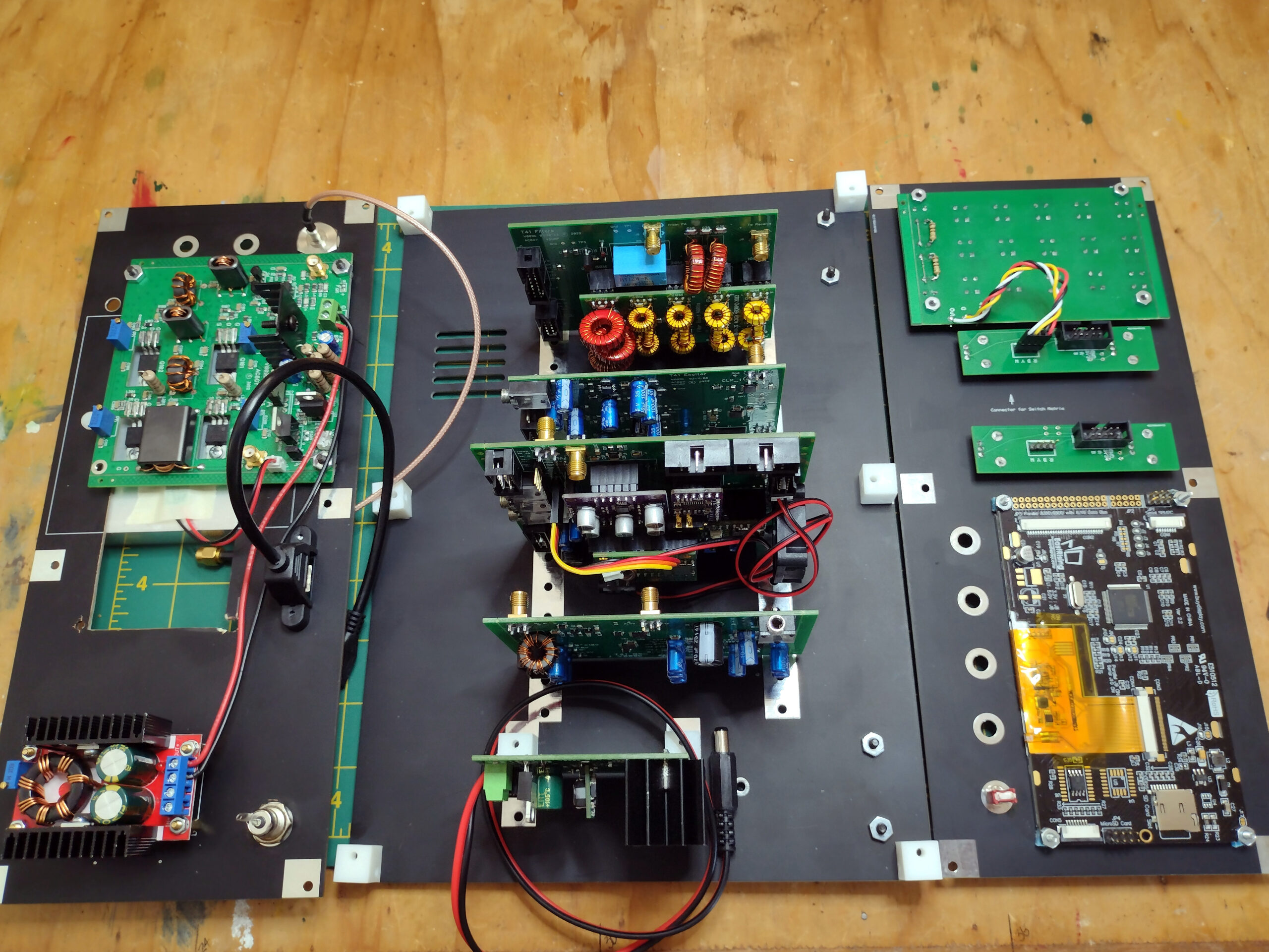
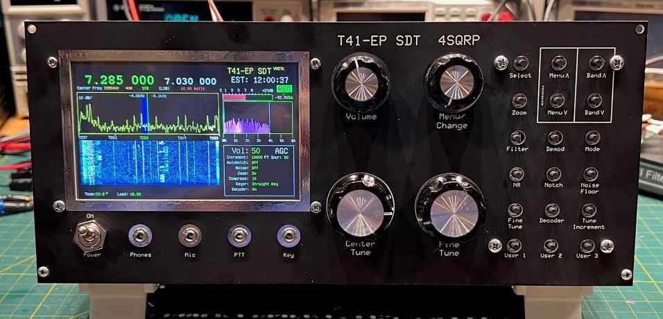
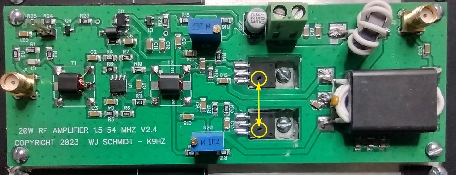
When we last visited this radio, it was almost complete. That’s when I decided to switch out the power amplifier. The “-EP” in the name means “Experimental Platform.” Let’s experiment. The reason is because of reports of poor power output on higher bands due to the original power amplifier using transistors with a very steep output falloff above 20 Mhz. A newer power amp has a much flatter frequency response at 20 watts output. (I only want 5, but will appreciate the extra headroom.)

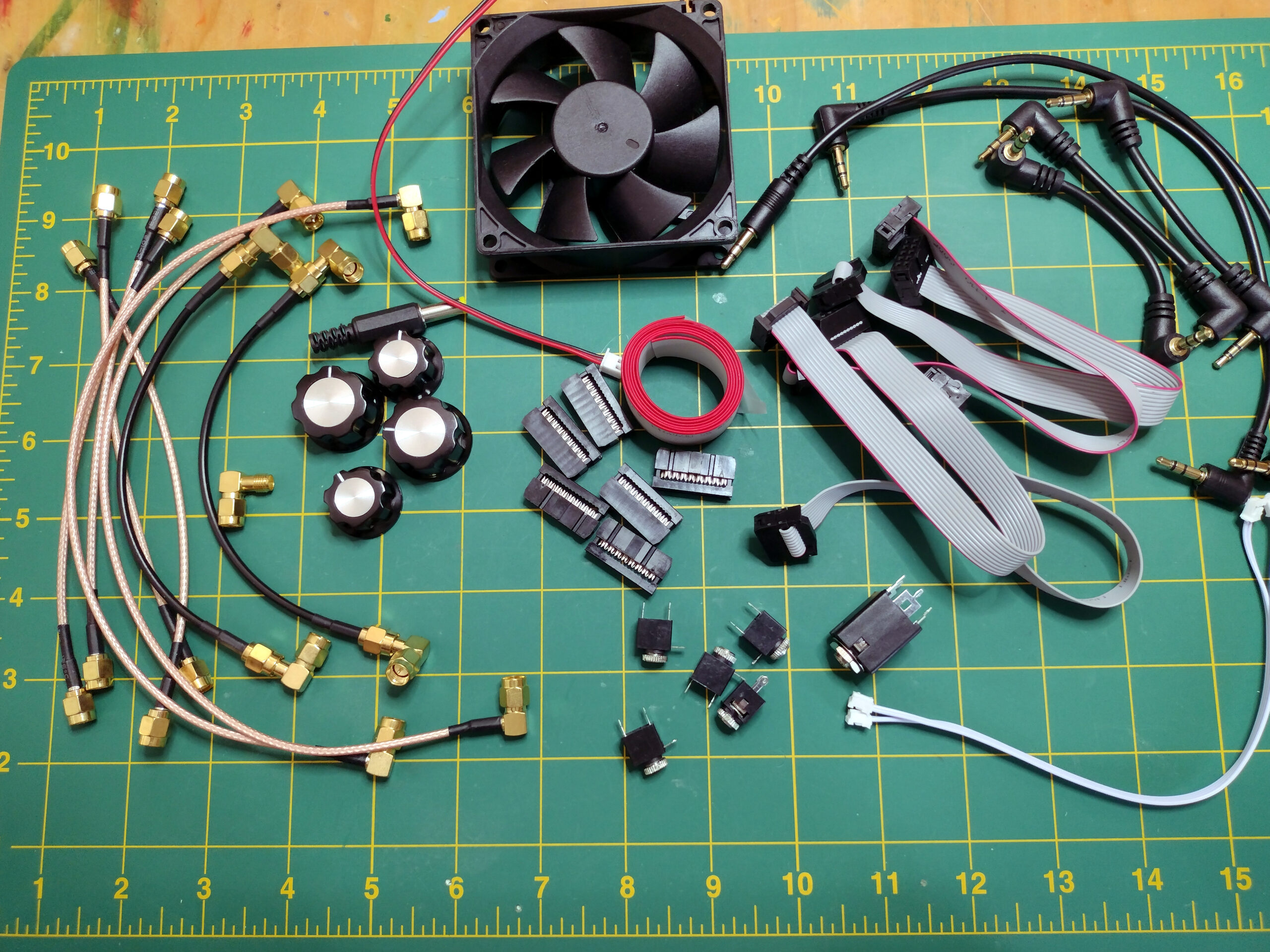
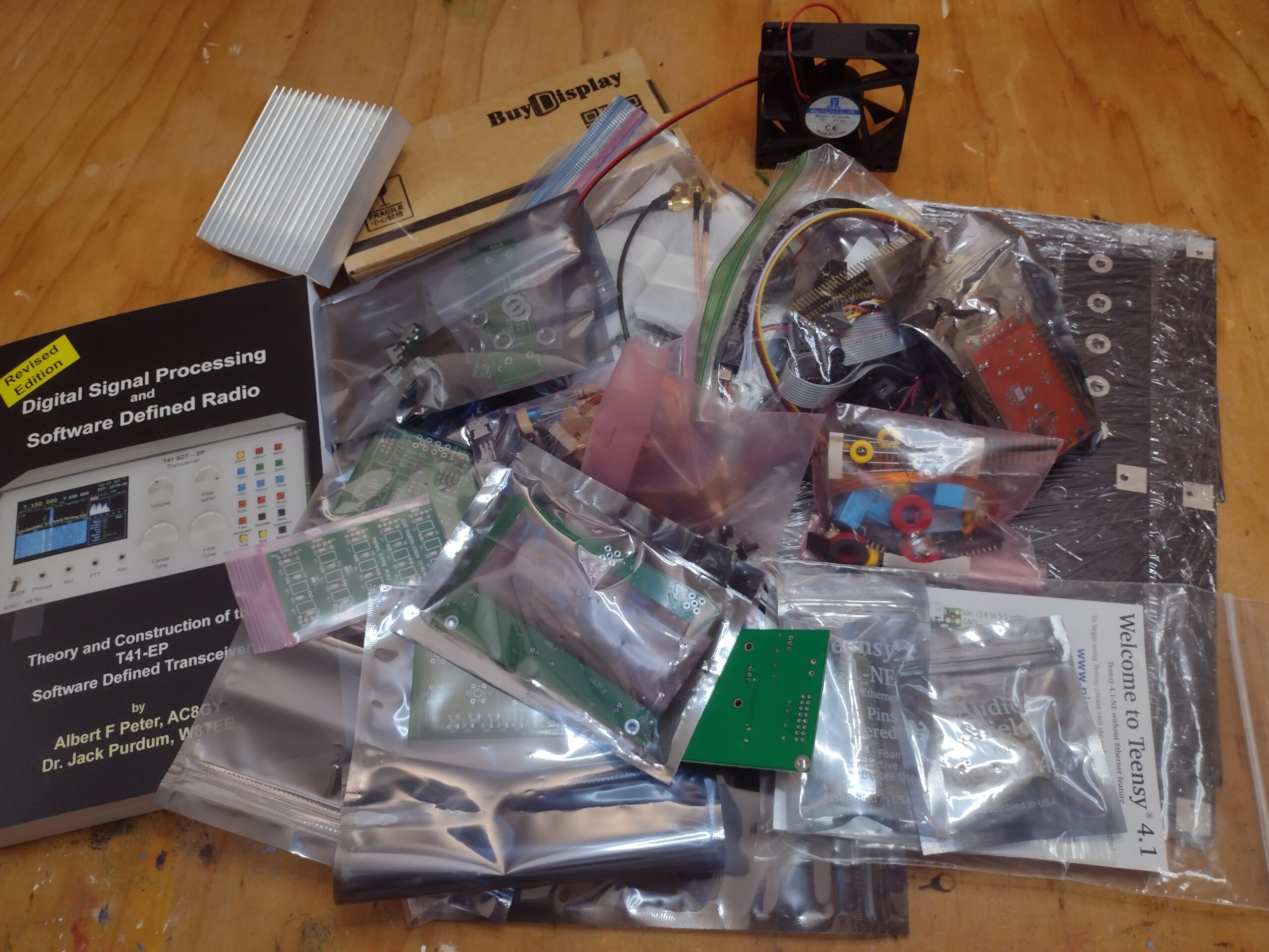
The semi-kit by K9HZ Bill Schmidt arrives as a PCB (Printed Circuit Board), a few semiconductors, a few transformer cores, some wire, and a BOM (Bill Of Material) for the rest of the parts. Almost all of the parts were SMD (Surface Mount Devices), giving me the opportunity to learn a new skill. 🙂 Despite needing a very good magnifying glass and a jeweler’s loupe, construction went very well.

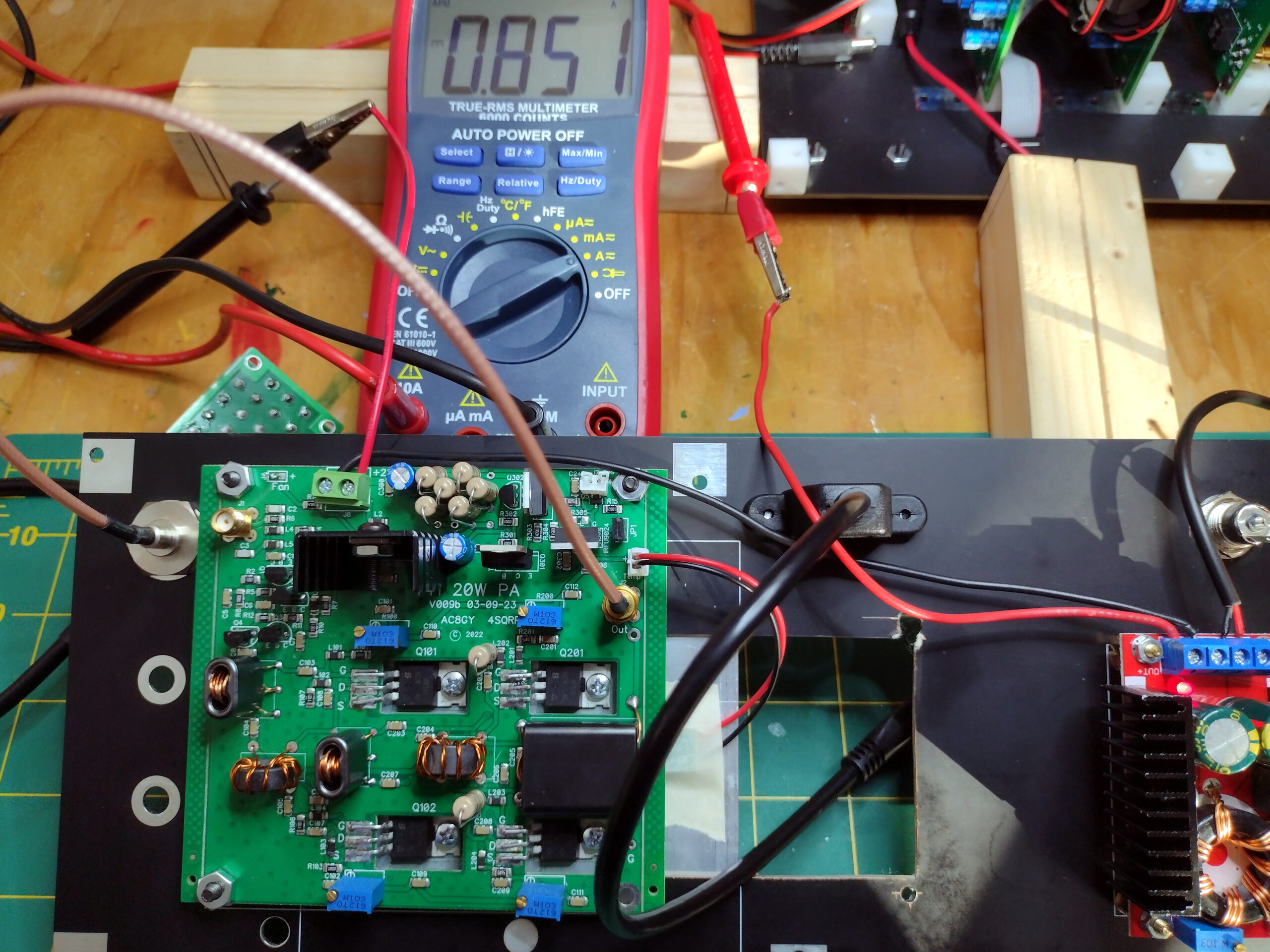
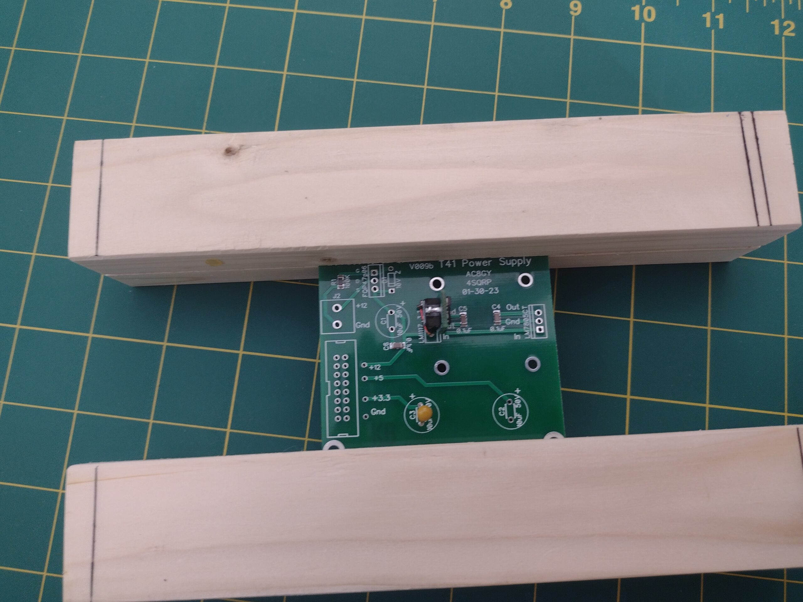
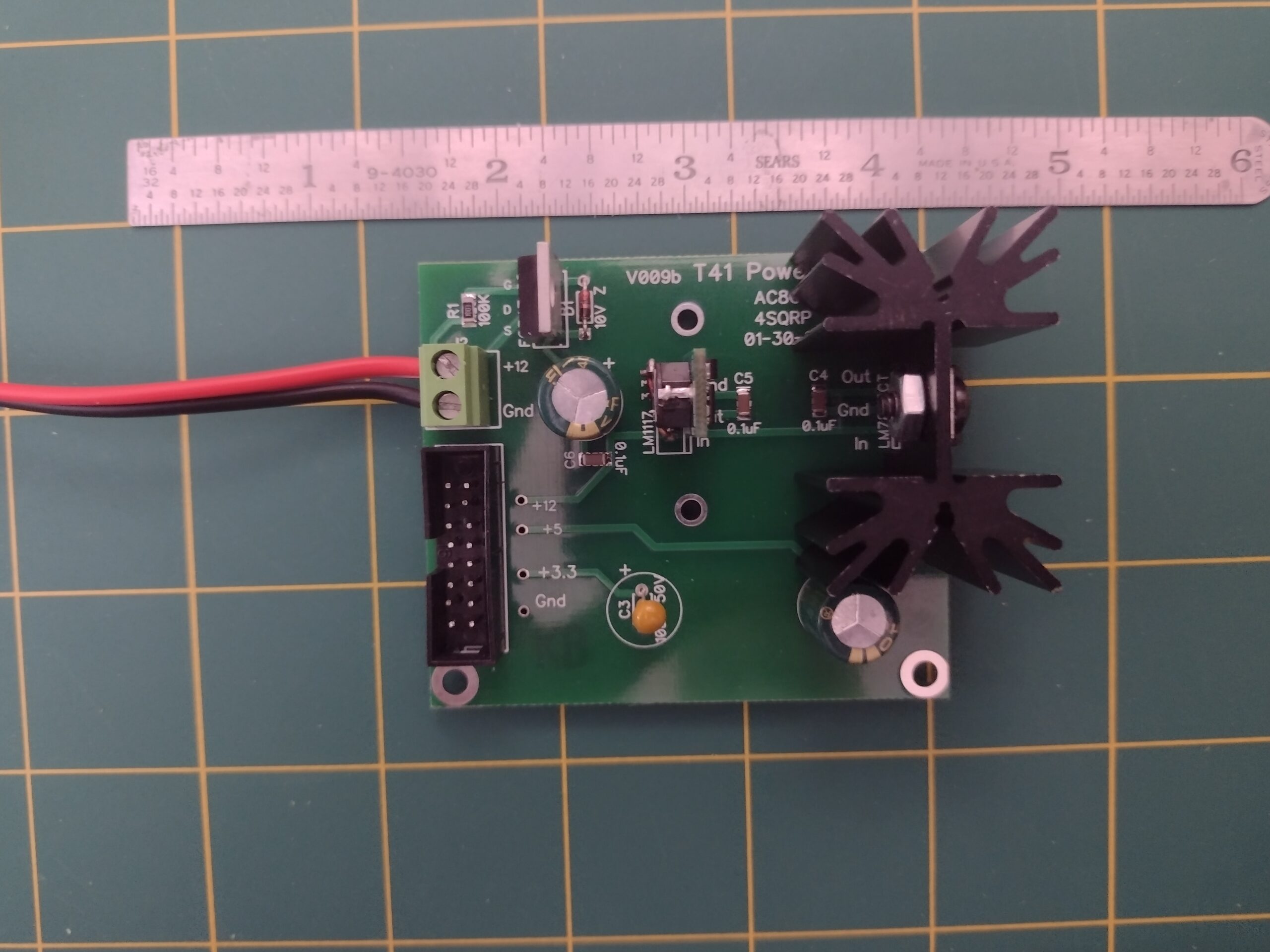
So did initial power testing. The fun came along at the next stage, when the “bias” potentiometers are adjusted to produce the correct current flow through each of the power transistors. For that, the amp needed a signal voltage from the transceiver. So, I mounted it in the case and hooked up power.

A very quick “POP-POP” was the response on flipping the rig’s power switch. Puffs of smoke from new holes in the power transistors floated up. All electronic devices are powered by smoke and once you let the smoke out, they no longer work. ;{

What the???? User error, of course. Wrong polarity power. I tried using a new battery, a new LiFePO4. It is a very nice battery that will serve well as a base station power source. My mistake was NOT making up new power cables, but using a couple that were in the box. Hey, these two fit together. I blithely went ahead without realizing that using them in series, instead of alone, produced a polarity reversal. Stupid error! … POP-POP and along with it lesser POPs and PFFFTs inside the mostly complete T41.

As I write this, I don’t know the extent of the collateral damage. After replacing a few parts on the power board, the rest of the T41 does not come to life and there are significant voltage drops on the 5V line. It may be time for an extensive rebuild.
UPDATE: There are enough “anomalies” with the existing build that I’ve decided to rebuild completely using the V12 version of the T41. More function, refined RF specs, and known-good hardware are some of the reasons.

Meanwhile, I can easily rebuild, and correctly test the power amp. It is independent of the main radio and easily rebuilt.

P.S. Safety glasses recommended for first power. In this case, it was under a magnifying glass which stopped the remnants.

Filed Under: radio, T41-EP Transceiver

T41-EP SDT (2 of ??)

May 3, 2024 by Bob Easton Leave a Comment

Construction is well on its way. All the boards are built and the transmitter has passed an important milestone. First a look at the assembly which currently consists of three panels.

On the left is the back panel which currently is home for the 20 watt Power Amplifier board and its boost supply. The middle is the base panel which is home for 5 boards, itemized shortly. The panel on the right is the front panel which accommodates the display, four encoders and an array of pushbutton switches.

photo of the 3 main panels

Back panel

The 20W power amplifier board is the V10 original. It is claimed to be able to produce 20 watts power output across the various bands, using 4 each IRF510 transistors. For this, it also needs voltage higher than the 12 vDC used throughout the rest of the rig. That smaller board is a buck convertor that bucks 12 vDC up to 25 vDC.

Since ordering this kit, I’ve learned that the transistors used in this amplifier have a very steep frequency efficiency falloff that reduces power in the 10M band to something notably less than 5 watts. I don’t care for 20 watts across all bands, but really do want at least 5. So…. there’s another power amplifier waiting in the wings, and it is the reason for that extra open space in the back panel. It will be the subject of another post where Bob learns to handle small SMD components.

Base panel

The 5 boards attached to the base are, from the bottom of the picture to the top:

  • the 12 vDC power supply
  • the QSD, Quadrature Sampling Detector, board where RF signals are prepared for digital signal processing.
  • the Main board which holds digital signal filters, the little Tiny 41 microcontroller which handles all the signal processing, system configuration details, and menu system. This board also houses interfaces for the display, encoders and pushbutton grid, along with some audio processing
  • the Exciter board produces phase shift and SSB, Single Side Band, modulation
  • lastly a filter board includes all the pesky toroids (aka torroids, or toeroids) for RF Low Pass and Band Pass filtering

All of these functions are concisely explained in Al and Jack’s book: Software Defined Radio Transceiver: Theory and Construction of the T41-ep Amateur Radio SDT. About 500 pages which include a deep drive in Digital Signal Processing.

Note: there is now a 3rd version, which adds information for V12, version 12, of this radio.

Front panel

Self explanatory, a display board, 4 encoders, 16 pushbuttons and various other connectors.

Milestone – PA biasing

Even though I intend to replace the V10 Power Amplifier with another, I decided to complete the initialization, or biasing, of this amplifier. Maybe it can be used elsewhere sometime. The process is simple, and avoids smoke and explosions if each of the 4 blue potentiometers are first set to their lowest values (many turns counter-clockwise).

Then, an ammeter is placed inline with a 12 vDC power source and power is applied. The desired result is a base line of 50-55 mA for the board. One by one the blue potentiometers are turned up (clockwise) until the power drawn increases 200 mA for each IRF510 transistor. The end result is a current draw of about 850 mA and no smoke. Success. Done.

BTW, the finned aluminum heatsink, with no fan, reaches about 140 degrees F.

photo of the bias adjustment setup

Next …

A whole bunch of interconnects, software loading, and various adjustment / alignment processes.

photo of cables, knobs, jacks, etc.
a whole lot of jumpin’ goin on

Filed Under: radio, T41-EP Transceiver

T41-EP SDT (1 of ??)

May 1, 2024 by Bob Easton Leave a Comment

The T41-EP is a Software Defined Transceiver designed by Albert F. Peter, AC8GY and Jack Purdum, W8TEE. The “T41” part of the designation comes from the fact that it uses the Teensie 4.1 microprocessor for software processing. The “EP” part of the designation means “Experimental Platform.” I started building Version 10 of the radio a couple of months ago, while Jack and Albert are now well off into version 12. Experimental — evolving.

The 4SQRP version of the T41-EP uses a 5″ LCD and enough front panel controls that one doesn’t have to be constantly digging through menus. That grid of buttons on the right gives instant access to many menu pages.

The picture is from the T41 site, not my build.

My interest is not the 20W capability, but the 15M, 12M, 10M capability. I’ll strick to QRP power levels, but want the rig for the bands. Yes, I have those bands with the “quirky Lil Orange” (tr)uSDX, but I trust the T41 will have more pleasing audio quality, and much easier operation.

My T41-EP

While the designers create circuits, PCB layouts and such, it is up to builders to either collect their own parts or find groups that are collecting parts for sale. One such group is the Four State QRP Group, 4SQRP, located in the Ozarks region of the U.S. A little over a year ago, they began a kitting operation to both promote the T41 and as a fund raiser for their club attending the OzarkCon ham radio conference. One interesting aspect of their sourcing is the provision of Printed Circuit Boards (PCBs) that already have the tiny Surface Mount Devices (SMDs) installed. Buyers are relieved of needing to acquire SMD assembly techniques. It was my very good fortune to snag a kit near the tail end of their run, which I think was 150 units plus a few betas. It arrived a few months ago and has not yet self-assembled.

My first job was making a “jig” to hold circuit boards. I think there are 7 or 8 in the kit. Instead of buying a fancy-looking collection of plastic, I wandered out to my woodworking shop, picked up a 2×2 cutoff, cut a very accurate kerf with my kerfing plane, and cut it into 2 pieces. Done!!! no waiting for Amazon.

The first assembly task is the power supply regulation board. It was an easy way to start and is now done and tested. AOK!

The assembly manual, about 120 pages, is concise and includes circuit diagrams, bills of materials, suggested build sequences, and in some cases test procedures.

A more extensive document, Software Defined Radio Transceiver: Theory and Construction of the T41-ep Amateur Radio SDT, is a 497 page book by the designers, and is a full fledged tutorial on digital signal processing using the T41 radio as the basis. It too holds extensive build and test advice.

Filed Under: radio, T41-EP Transceiver

Primary Sidebar

Solar-Terrestrial Data

Solar Ham

find the latest solar weather conditions

What’s happening NOW?

Recent Posts

  • AX1 “dummy load” rides a Trike
  • QMX+ First run
  • Yet another CW tool from Mike and Becky
  • New QSO Finder tool for CW operators
  • CW Learning Forever

Copyright © 2025 · Bob Easton · N4REE