Roger Davis is a fortune teller, and a fellow Hoosier.
Roger and I met quite awhile back over on the Sawmill Creek forums talking about, what else, old tools. Not long after I published the last entry, Roger advised that the walnut crank probably wouldn’t last long. Now, it hasn’t actually failed but it didn’t take long for a bit of wobble to develop. Roger is a fellow woodworking enthusiast who also has day-job metal working skills and the equipment for prototyping aerospace instrumentation. Roger offered to make a “bulletproof” steel crank and I took him up on the offer. I’m absolutely amazed that he offered and acted so quickly. The crank is here and already in use. THANK YOU Roger!
By the way, for the spalted maple fans, be aware that there’s such a thing as spalted steel. This crank has a bit of spalting which I consider early onset patina.
The Treadle Mechanism
When I was much younger and more interested in high performance automobiles, one of the things I learned about was “unsprung weight.” That’s the weight of the car in the wheels, axles and undercarriage that isn’t moderated by the suspension system. A lot of unsprung weight dampens a car’s performance. The lower the amount of unsprung weight, the better performance can be tuned. This lathe takes that approach with the treadle. I’ve seen a lot of treadle lathes that have huge heavy treadle mechanisms. It seems to me that the effort that goes into operating a heavy treadle has the same dampening effect as excessive unsprung weight in cars. I can appreciate how a heavy flywheel adds momentum, but not if it has to drag along the dead weight of a heavy treadle. The lighter treadle was part of what drew me to this design.
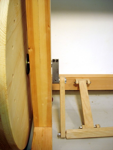
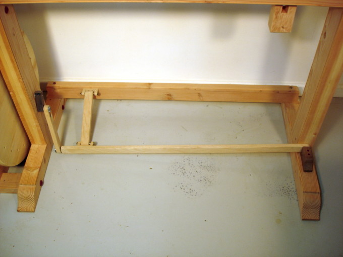
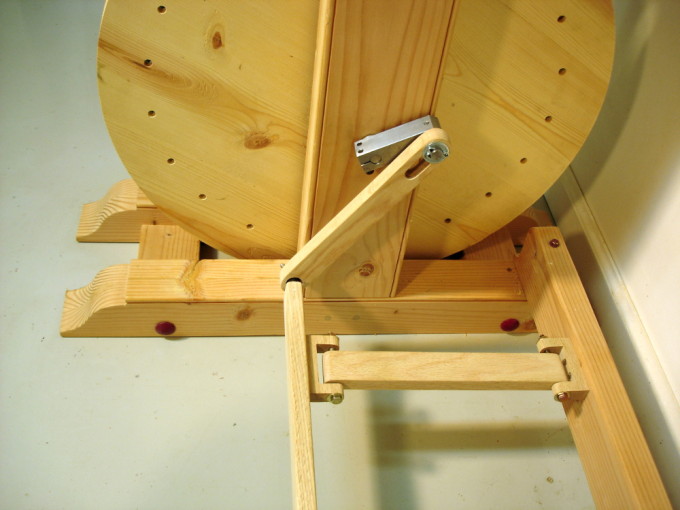
Three lightweight parts comprise the moving components, the treadle itself, a Pittman link, and a spacer bar that keeps the treadle parallel to the center line of the lathe. All three are of oak approximately 3/4″ by 1-1/2″ in measure. The treadle pivots on a 1/2″ diameter pin that’s held in the walnut block on the foot of the right leg. The pivot hole itself is 3/4″ diameter providing enough play for easy operation. The driving end of the pedal holds another 1/2″ diameter pin that engages the Pittman link. The bottom hole on the Pittman link is also 3/4″ diameter, allowing for a lot of angular movement. At the top of the Pittman link is a slot that is “a whisker” larger than 1/2″ wide, enough to ride freely on the crank’s 1/2″ diameter drive pin. Two u-shaped oak blocks anchor the spacer bar. The anchor pins are 1/4″ bolts fitted in 1/4″ holes in the blocks. The pivot holes in the spacer bar are 5/16″. Thinking these parts might need lots of wiggle room, I tried a much loser version and ended up with a lot of clunking. The tighter version runs smoothly and without any binding.
As before: Il meccanismo è molto scorrevole!
First Turning – a 24 inch object
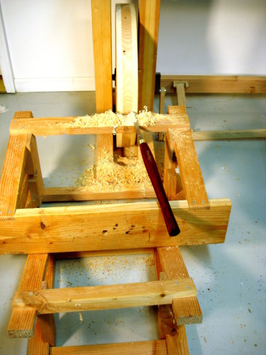
A couple of posts back, I mentioned that the flywheel was cut round using a jig on the band saw. Well, that “round” was approximate. It wanted some truing, not a lot but enough to make me wonder about how well a belt would track. How to get it trued up? Makeshift time!
Finding a “tool rest” of an appropriate height was the first challenge. What the photo shows is an alternate use for the pair of saw benches I made ages ago. Flop them over on their sides and stack them “just so,” and the result is something good for supporting a newly arrived round nosed scraper. Not having a readily available treadling apprentice, I parked a chair beside the upturned saw benches, sat down, and treadled while leaning over and holding the chisel.
The wheel is now round. The drive belt won’t have to put up with a roller coaster ride. If you watch the wheel turn, you’ll see some side-to-side wobble, for which there are two responses: don’t watch, and it’s not enough to affect operation. 🙂


Looks real nice Bob. What’s the first project now that the wheel is round?
Just thinking out loud – would cutting a slot in the floor to allow for a larger diameter wheel give you a performance boost? (or raising the lather up) I’ve watched Sir Roy use his treadle lathe for years and it has always fascinated me. A lathe is one woodworking tool I don’t know how to use.
ralph
Hoosier? I am from Kokomo and was the host of the notorious Hoosier Galoots gatherings a dozen years ago. I would love to come and see your lathe. I am hoping to build one soon.
No crown on the wheel to help the belt track? I suppose you can always add it later if it’s needed.
Ralph,
The first turning project will be making a proper drive wheel. Just wait til you see the temporary contraption I’ll use to get started.
Ron,
Hoosier born and raised. I once lived in Kokomo while working for Uncle Sam when that place up the road was called Bunker Hill AFB, back when it was used as a counterweight to Soviet nuclear power. Now, we’re a bit farther away, in the great “Empire” state, NY. It might be a long drive, but you’re welcome to stop by.
Boy,
The crown was added since those photos were taken. It is a slight crown, with each edge is about 3/16” lower than the center. We”ll see how it works or if more is needed.
That is a nice looking treadle and good job with the improvised tool rest. Never having put together a race car, but being an avid race fan, I understand what you mean by ‘unsprung weight’ (they talk about it all the time on F1 races). Are you planning on using a cord or leather belt? One trick I read that Roy Underhill used with his treadle lathe was a leather driver cord that he wrapped in an elongated figure-8. He had a tension wheel but found it was too fiddly and the figure-8 worked just as good.
Joe,
You’ll see a leather belt coming up soon, along with an explanation of why I chose a belt over a cord.
Hi Bob,
…….long time reader first time poster…….. sorry I had to..
from and engineering stand point you can use the heavier treadle as additional mass for the wheel rather than treating it like unsprung weight by adding a counter weight to the wheel on the opposite side of the axle from the lever arm that is the same weight as the treadle. this will balance the rotational mass as well as increasing it and cause it all to run smoothly.
Cheers,
Jeremy
Jeremy:
Bob’s got it about right. The lighter the treadle, the less mass to be accelerated (and it is constantly (but not uniformly) accelerating). Force = mass x acceleration, force through a distance is work, and this work is energy removed from the flywheel. This is NOT a balance issue, it is a question of keeping energy available in the flywheel to do work ON THE TURNING rather than waste it moving a treadle up and down. A more apt comparison than unsprung weight in the suspension of a car is the use of lighter forged connecting rods to increase engine performance. The heavier the rod, the more energy is sapped slamming it back and forth. A light treadle is both easier to accelerate by the user and steals less energy being pulled up for the next stroke.
RD
Jeremy and Roger,
Thanks for the engineering observations.
My own engineering started as electrical (Purdue, late 60s), not in physics or mechanical. As a computer enginerd, I’m not fully qualified for the mechanics of flywheel driven devices, but I think the connecting rod analogy is a good fit.
in the event that you were trying to suddenly stop or reverse the movement of the mass you are completely correct roger but since the treadle is linked to the rotating mass of the flywheel by the arm the mass of the treadle is being moved counter to the flywheel constantly. adding a counter balance to the flywheel opposite the position of the treadle will balance the whole moving assembly. it is roughly the same principle as balancing a car tire by adding weight opposite the heavy spot on a tire. keep in mind that as light as the treadle is that you built Bob at low rpm you will not notice it, as the rpm increases though the vibration will be amplified. much in the same way that a car tire out of balance will run smoothly in town but at 70 on the highway will about jar your teeth out. Roger is right about the acceleration 100% but rather than working against the mass of the treadle you can use it to your benefit. the greater the rotational mass the more effort it is going to take to get it moving but that also means that it is going to take more effort to stop it as well. making it easier to turn larger objects. the mass of the object being turned is going to directly act on the rotational mass of the complete assembly each time a tool is applied to it.
hopefully this explanation is a little better than my initial one. Roger and i are basically saying the same thing we are just applying it differently to individual parts.
Thank you Roger for taking the time to respond to my initial post. Bob thank you for the wonderful walk through on this build.
Cheers,
Jeremy
It still sounds to me Jeremy that you’re far more interested in balance than the raw effort needed to make the thing move. Following your own argument, one needs to add a counterweight proportional to the weight of the treadle. The heavier treadle you suggest needs a bigger counterweight.
I’m not buying it. Right now, balance is definitely NOT a problem and I need no counterweight at all. I am able to achieve very good balance (wheel alone) by adjusting the position of the crank Roger made, an element that weighs about a pound.
No vibration as fast as I can turn the wheel by hand. Add the treadle and pump like crazy: no vibration.
Now, why would I want a much heavier treadle and also have to add the same amount of counterweight to the wheel? There may come a time when I really want the wheel to be heavier to provide momentum, but not because it needs to be heavier to balance an overweight treadle.
your right Bob i am definitely interested in balance. I hope I have not caused any offense with my responses that was not my intent and i sincerely apologize if i have. stable movement is caused by all parts being balanced, and the greater the weight being moved the more force it will take to get it moving but the more force it will take to stop it from moving as well. The most important thing however is not the physics involved but the much more important variable of “does it do what you intend it to, did you enjoy building it, and did it come out beautifully?” I think it meets all the requirements in spades. Bob you do beautiful work and enjoy greatly your blog.
Cheers,
Jeremy
Well now the equation F=ma has come up in a blog comments about a hand tool. I can say that I have seen it all. Great work on the improvised turning Bob!