The last 15 years of my previous career were spent in the world’s finest commercial research laboratory. From there, I learned a method of working that leads me to do a good bit of research at the start of a project, to learn a great amount about a subject before starting the actual work. I continue that practice with my woodworking projects, often collecting many more plans and articles than one could ever use, and then building to none of them.
Plans
My first article about building a lathe touched quickly on the sources of a few plans for lathes. By “plans,” I mean publications that include measured drawings or enough detail to be useful as construction guides. Here are a few more details along with some of my opinions.
Roy Underhill’s treadle lathe article describes a lathe built from discarded lumber salvaged from the dumpster outside a university dorm. This article comes to us compliments of the Woodworking magazine blog, originally published in the October 2000 issue of Popular Woodworking magazine. Underhill’s usual humor augments the constructon details for a lathe is smaller and lighter than the one Roy often demonstrates on Woodwrights Shop TV program. It fits very well with the idea of using standard size construction lumber and has a number of features that simplify construction, such as connecting the pittman arm directly to the flywheel instead of fabricating a metal crank. While a nice feature, it requires the flywheel be cantilevered, and I wonder about the durability of such an arrangement. An appealing added feature is a lightweight scroll saw attachment. I definitely want to use this idea, but will build one a lot more robust.
All in all, this is a fine article with a very complete cut list, good instructions, and a bit of Roy’s humor. It strikes me as a fine “starter” treadle lathe.
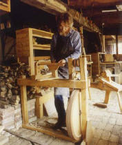
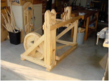
Steve Schmeck keeps a website covering a variety of topics, many of them environmentalist in nature. His lathe plans have been available for several years. Steve’s lathe is quite a bit like the pictures published in the first of these lathe articles, substantial in size, but still manageable for transport in his van. It lacks the diagonal braces shown on some designs. An added feature of Steve’s lathe is an optional tension adjuster that alleviates the chore of resewing a stretched drive belt. Like all of the lathes I considered, construction is from construction grade lumber with hardwood mixed in where you think appropriate.
You bike riders might want to check out Steve’s homebuilt “Woody” recumbent bike. Yep, a wooden bike.
Mike Adam’s lathe is somewhat similar in size and construction to Steve Schmeck’s. He does the various bearings and the crank a bit differently, housing bearings in hardwood inserts. His foot pedal is a full width frame, not just a single board as in the previous designs. Being a bit klutzy, this wider pedal holds appeal for me. Mike’s spoked wheel looks great, but he admits it was too difficult to construct and needed additional balancing once done. That’s why I decide on a solid wheel. While updating this article, I find that Mike’s web presence has sadly disappeared.
Update (Oct, 2022): Stephen Shepherd’s website has disappeared from the interwebs. A couple of years ago, I heard he was having health problems. I certainly wish him well and will leave his link here in case he gets back on the air.
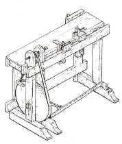
Followers of Stephen Shepard’s Full Chisel blog will recognize Stephen as a restoration specialist and expert artisan for nineteenth century woodworking (from the turn of the century until “the unpleasantness between the states”). Stephen’s plans are available from his own online store. True to form, Stephen’s plans are excellent, drawn from an 1805 exemplar. They are very complete, comprising eight 11″ by 17″ plates and 4 pages of commentary. This lathe is distinctly different from the others, being a combination lathe and workbench. The wheel is more forward, pivoting from within the headstock uprights instead of from diagonal braces further back as in all the other designs. A bench surface extends rearward for 12 inches beyond the spindle centerline and is the full width of the lathe. A small vise attaches to the back edge of the bench. It is a clever design for those pressed for space. Also interesting are the several purpose built, hand wrought, chucks. They appeal, but will require finding a blacksmith.
Lastly, I referred to web material by Howard Ruttan. His is, alas, not a set of plans, but a comprehensive FAQ with yet more links to research.
Lams
Many of the lathe components need to be thicker than typical construction lumber. Thus, we laminate. My nearby home center stocks the usual number 2 lumber that’s useful for framing. Like most of this stuff, the narrower pieces are the worst available, often being milled from trees barely large enough to contain a single 2×4. I buy much wider boards and rip them to the widths I want. One good feature of most of their lumber is that it is reasonably dry and does not need a lot of acclimation.
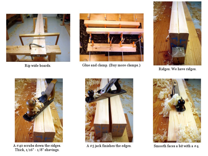
The lamination process is simple. It consists of these steps:
- Plane the intended faying surface enough to ensure a good join. This is most useful to remove cupping; planing only the faces that will join each other. The jointer plane is your friend here.
- Rip.
- Glue and clamp (currently using yellow carpenters glue). When laminating, ensure stability by having the outer edges of the board, the edges toward the bark, face each other. The end grain should look like this: )))(((
- Plane off the crowned edges (if any), using first a scrub (#40) and then a jack (#5).
- Remove most of the surface uglies with a smoother (#4).
Effort and energy cost: about one Snickers bar per 10 foot lamination.
Bob,
Great research and background material – I am looking forward to this lathe and, later, its use. I hope you will find a good enough supply of the Snickers bars locally; but, if you don’t, just give a shout… 😉
Al
What about adding a simple or spring driven oscillating drive converted rotary motion with a ratchet and pawl or even a bicycle freewheel and use some weight lifting weights for a flywheel on the drive center shaft ?
Opps. I meant, what about a spring pole lathe with a rope drive? The oscillating motion could be converted to rotary motion with a ratchet and pawl like a bicyle freewheel? That would save making the fancy flywheel and would let you put everything, including heavy flywheel directly on the drive center shaft. That could mean many fewer parts and maybe better efficiency than a crank on a big wooden flywheel.