Clackety-clackety-clackety thunk-clackety-thunk. What a contraption! Roy says, “Won’t the kids be proud!” Well, maybe … if they don’t run off scared.
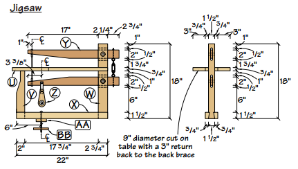
Well, it’s time. I want one. Actually, I want a scroll saw, not a jigsaw. The distinction I make is that Roy’s jigsaw was designed for relatively coarse coping saw blades. My first want is for cutting out blanks for woodcarvings, blanks that can be 1″ thick or more. Coping saw blades are OK for this. Yet, I also want to do finer work with tighter turns than one can get with coping saw blades. There’s where fine scroll saw blades are needed.
Roy provided just enough information to build a saw that’s just about works. I had just enough scrap wood to knock together a “semi-beautiful” prototype made of 4 different kinds of lumber. Even as a prototype, I changed a few things from Roy’s drawing:
- My lathe center is a higher height from the bed than Roy’s. So, I extended the dimensions for the arm pivot points accordingly.
- I made a different crank. Roy’s plan suggest a bent crank that replaces the lathe’s spindle. Having long ago discovered the town smithy left for lower taxes elsewhere, I modernized my lathe spindle to use standard 1″x8 lathe chucks. I thought long and hard about the crank. Roy’s plans called for a 1/2″ crank pin with a 1″ throw from center.
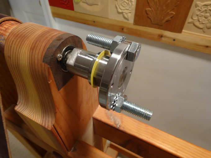 Reluctant to go find a machinist (a title I once had in the USAF), or to beg a favor from my Hoosier acquaintance Roger Davis, I decided to “adapt.” I think that’s French for “make something work.” I found a 3″ steel faceplate that had a circle of 4 holes that are 1/4″ in from the edge.
Perfect! Drill 2 of those out to 1/2″ and use 1/2″ bolts and nuts. One bolt, star washer and nut points away from the plate and becomes the crank pin. A partner bolt, star washer and nut points toward the headstock and is a counterweight. The result a crank with a 1-1/4″ throw, 1/4″ more than plan, but what’s a 25% difference among friends!? (more on that later) - The tiny drawing didn’t show details for the blade mounts, but the article did suggest hacksawing the ends off of a coping saw and using those. I tried something similar, by using clamp style ends from a jeweler’s saw. That approach would be good for non-pinned blades. It turns out they don’t hold well enough. So, I replaced them with excellent brass saw pins that I used for my turning saw. They’re are Gramercy Tools Turning Saw Pins from Tools for Working Wood. These pins are for pin-end blades and are beautiful when compared to any coping saw blade holder.
- I made my crank link from oak and fitted it with ball bearings left over from building the lathe, and a single piece of iron strap to attach it to the lower arm.
My first reaction to using it was to call it “the contraption.” The action was very wobbly. It clattered around with a LOT of thumping and rattling. The blade, being at the ends of long arms set on moderately imprecise bearing points, moved with a lot of “dancing” action, much like a very wide and jerky do-si-do. It worked, but as my wife says “it looks like a great exercise machine.”
Yet, it does cut, if the turnbuckle is properly tensioned and locked and all the rest of the connections made secure enough to not rattle apart. My first trials were with box-store coping saw blades and were promising enough to encourage me to see if scroll saw blades would work.
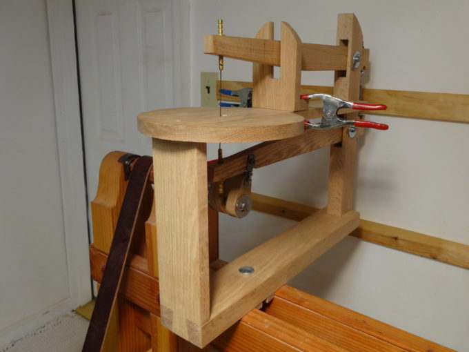
Scroll saw? Yes, but… It needs some adjustments, erm… improvements. Let’s set aside the first version and build Mark II. It is very similar, but refined in several ways. And, it’s completely constructed from oak, rather than 4 different woods used for the proof of concept version. Two pics: from the back (note the trunbuckle and lock nut), and from the front (with an adjustable arm guide).
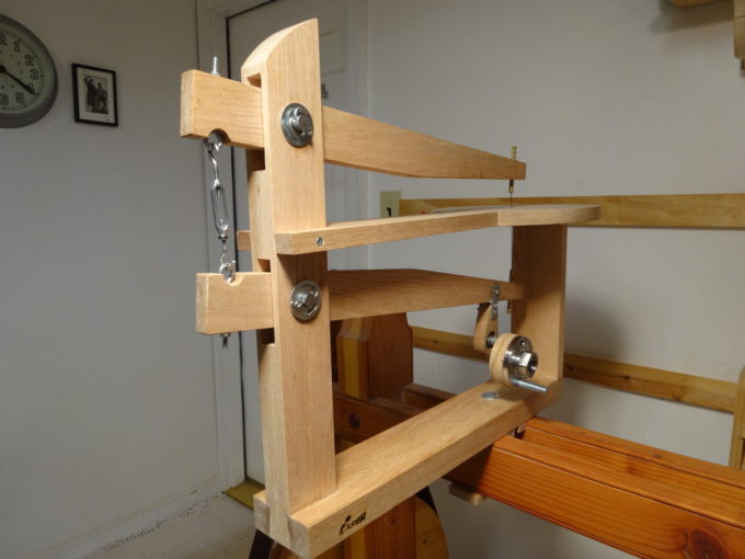
- The pivot points of the arms were changed so that the arm baselines are parallel when using my preferred blade, in this case 5 ” scroll saw. Coping saw blades will still work, but the motion is now optimized for scroll saw blades. I made sure these were sized using the Gramercy pins. Hint: If you do this, just lay all the parts out on a large piece of paper and measure. You don’t need precise SketchUp drawings.
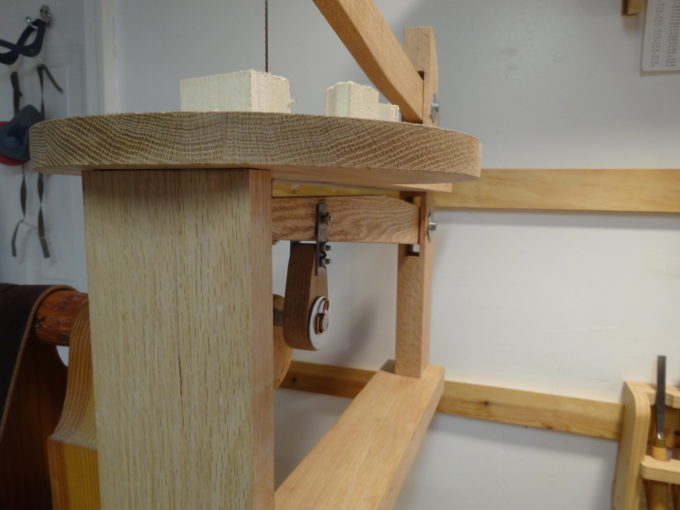 A new crank link embraces both sides of the lower saw arm. The Mark I version attached to only one side of the arm and contributed to the dancing action. Roy had this right. I took a shortcut with Mark I and learned from it. The new crank link is the same thickness as the lower arm. It houses a pair of bearings and has straps on both sides, providing much better lower arm stability. Not wanting to simply attach it with a screw that will eventually chew through the wood of the lower arm, the link is attached to the lower arm with a length of 3/16″ OD brass tubing. Inside that tubing is a 1/8″ screw and retaining nut that does nothing more than keep the tube in place.
- The distance between the end of the crank link and the bottom arm was tightened up. Reducing that distance allowed the table to be lowered 5/8″ and allows cutting material about 1-1/4″ thick with scroll saw blades, thicker with coping saw blades.
- The eye-bolts on the first version were too close together, leaving too little room for enough turnbuckle adjustment. Sinking the eyes half their diameter into the arms affords plenty of adjustment.
- The table position of the Mark I didn’t accommodate a 1″ work piece. I want to be able to cut blanks for woodcarvings that are 1″ thick (or more sometimes). A test with basswood did show very nice “dimpling” where the brass pin from the upper arm banged the top of the board. Adjusting the crank link clearance and changing table height allows for sawing thicker material.
- The Mark I had bronze bushings only in the arms, but not in the tower they swing from. It didn’t take long to realize the inaccuracy of these pivot points was contributing a lot to the clatter and dancing. Mark II has bushings in the arms and the tower. Better! Much less do-si-do, and I expect much less wear over time.
- Being eager to see if it works, I used 1/2″ x 2″ bolts and nuts as pivot axles on the Mark I. They worked, but contributed to the rattling and clattering. Those bolts were replaced with 1/2″ bar stock and cotter pins. This alone makes a huge difference. In the case of arms with bushings and the tower with bushings, “waggle” measured at the end of an arm is about 1/8 – 3/16″ with a bar axle. It was 3/4″ with a bolt axle – an amazing 5x to 6x difference!
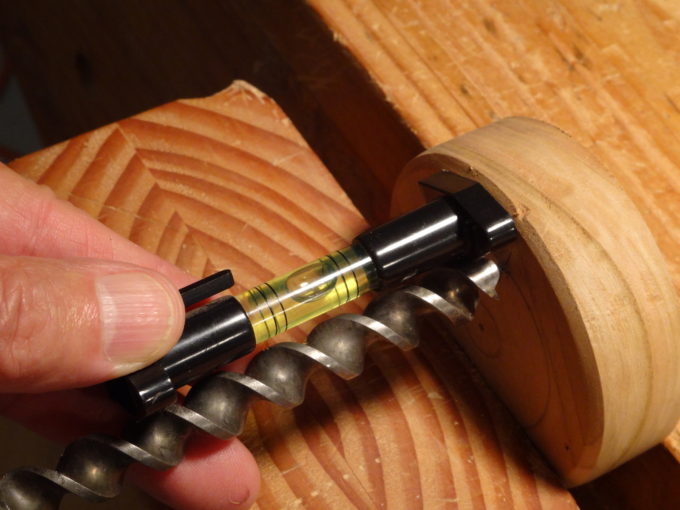 All of the bearing points are as plumb as I can make them without a drill press. Careful fitting with a rat-tail file and epoxy got them to acceptable precision. By the way: My method for checking uses a small level. I don’t recall when or where I got it, so can’t recommend where to get one. What makes this one handy are legs that have “V” notches in them. It’s easy to sit the level on a long piece of bar stock and make adjustments as needed. It’s also very handy for hand drilling. I prefer to clamp the work piece vertical and drill horizontally. It’s very easy to be square in the left-right axis that way. For the up-down axis, use the level on the drill bit. The result comes very close to what one gets with a drill press.
- Even with all of that extra care, there’s still more dancing than I want. The problem comes from the lower arm being nicely fixed near the blade, via the drive crank. It’ doesn’t have room to wobble, if the crank pin is true. However, the top arm has only that pivot point way at the back, allowing the blade end plenty of movement. Tight tensioning of the blade helps control that arm, but not quite enough. My solution is a yoke that can be positioned where needed to guide / tame the upper arm.
By the way, a lock nut has been added to the turnbuckle. After tensioning a blade, tighten up the lock nut. Otherwise, the motion of the arms will loosen the turnbuckle and the blade will go flying. Yes, safety glasses are a good idea! A note on tension: the tighter the tension, the more friction in the movement. Too tight and the saw won’t operate smoothly. Too loose, and the blade won’t follow a curve smoothly. 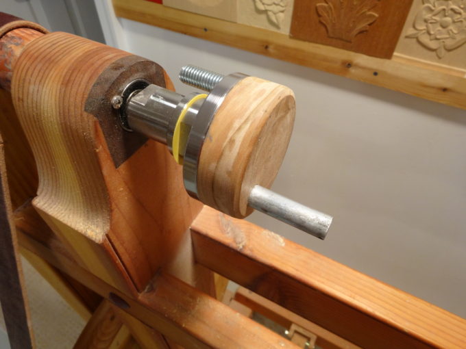 It turns out that the extra 1/4″ throw, from using the easiest place to put the crank pin on the faceplate, means added friction (and energy) at the horizontal inflection points. It takes a lot to keep the motion going through those points. Maybe Roy’s 1″ throw was right? So… out comes the 4-jaw chuck and an experiment to reduce the throw back to 1″. A pin set at 1″ offset can’t be held very well in my chuck, but it was enough for a trial. What a HUGE difference!!
Now, to make a more permanent version…A bolt, or crank pin, can’t be moved in closer on the faceplate, toward the lathe axis, without running into the spindle. So, put the crank pin through another plate. My next step was to create a wooden plate (cherry), and drill a hole for a 1/2″ pin. The pin is epoxied in place with JB Weld. JB Weld sets up in 4-6 hours, giving plenty of time to ensure the pin is square to the faceplate. And yes, I included a bolt facing the wrong way as a counterweight. The crank is well balanced; there’s no vibration from the crank.
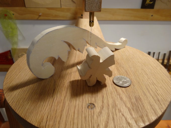 The pieces in the last photo were practice exercises, in effect the “final exam” for whether the saw can do what I want. The saw passed the exam, but the sawyer needs more practice! The Acanthus leaf is 3/8″ thick basswood, and easily cut. The smaller piece is a dragon’s claw, only a fragment of a much larger carving. It too is basswood, 1″ thick. The blade is extra fine 18 TPI, leaving a very smooth surface.
TAMED!!! Now, I’m happy. I can cut carving blanks with the detail I want. It is not a saw for very fine fretwork or for cutting wooden clock gears, but it does what I want.
Bob
are the TFWW pins just a friction fit? Nice build and I liked the explanation of the steps.
Yes Ralph, they’re only friction fit. … and haven’t moved yet. I don’t think I’ll have a need to rotate them, but can if I want. A little dab of epoxy will fix them if they ever start wandering around.
The most fussy part of the machine is the crank. When it is off only a frog hair, the bottom arm, and consequently the whole blade, wobbles. Knowing your level of patience, don’t put this thing on your to-do list. 🙂
Fantastic build Bob and a great write up on the process!
I applaud your patience. I’m afraid my sanity would fall into question after trying to suss out all those idiosyncrasies.
Thanks Greg.
As Ralph sometimes says, I came close to “giving it flying lessons” several times.
You’re showing your patience too, with the Japanese planes. It’s delightful seeing those long ribbons.
Keep havin’ fun!
Wow!
Such a great detail report and a very useful report for my future (a not distant one I hope) 🙂
Thanks for this one Bob!
Thanks Antonio.
Very nice, Bob. I’ve wondered how that scrollsaw in Roy’s plans would actually pan out. You’re the only person I’ve seen on the Interwebs that has built it.
Thanks Derek.
“You’re the only person I’ve seen on the Interwebs that has built it.”
There’s always someone crazy enough. 🙂
This is fantastic, Bob. Being able to use the treadle base for two machines is a real space saver. I, of course, don’t have room for even the lathe, but I’ll dream about making/having something like this. I’m sure you’ll really enjoy this.
Thanks Matt.
Don’t even think about it. Your shop doesn’t have room for another quart of air, let alone a lathe and scroll saw. 🙂
Hi Bob Nice job, I will attempt to make one following your instructions, one question-at what speed is your lathe going at? my lowest speed is 425 rpm is this too fast ?
regards Tom Elliott Brisbane Australia.
Good question Tom…
I don’t have the slightest idea. My lathe is a foot-powered treadle lathe and I have no way of measuring its speed. Nor, do I have experience with a powered lathe that I can use for comparison. I do slow down from normal turning speed when using the saw, and I suspect that its a lot slower than 425.
Sorry I can’t be more definitive.
Have fun with making yours as smooth operating as you can and let us know how it turns out.
Good afternoon. Good job. From what you use a saw blades in the scroll saw and what length?
Hello Anatoli,
The blades are 5 inch (12.7 cm) long, and have pins at the ends.
Hi Bob,
I really like your post and the scroll saw! It is so good to run into others with similar passions. Years ago I read the same article by Roy Underhill along with other publications and had the same bug to build a foot powered scroll saw. I did a small piece for Woodworkers Journal April 2016 issue (p.19) that featured my “Victorian Scroll Saw” which is chain driven and a stand alone machine. I tweaked it a lot over several years.
Blessings,
Jim
Thanks Jim!
It’s always good to have a reminder to go see what others are doing. Thanks for stopping by.
For those who don’t know of Jim Paulson, check out his beautiful chairs, Windsors, ladderbacks, and others. Check Jim’s blog too, especially the Victorian Scroll Saw he mentions above. His is on the opposite end of the scale from mine; finer woods, worksmanship, and decoration. (inlaid saw table? decorations on a scroll saw that needed a scroll saw to create!)
Grateful,
Bob
Thanks for the kind words!